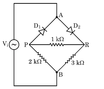
An ac voltage V is applied between points A and B in a network of two ideal diodes and three resistors as shown in figure. During the positive half-cycle of the input voltage V_i supplied to the network.
(a) Identify which of the two diodes will conduct and why?
(b) Redraw an equivalent circuit diagram to show the flow of current.
(c) Calculate the output voltage drops V_0 across the three resistors when the input voltage attains its peak value.
An ac voltage V is applied between points A and B in a network of two ideal diodes and three resistors as shown in figure. During the positive half-cycle of the input voltage V_i supplied to the network.
(a) Identify which of the two diodes will conduct and why?
(b) Redraw an equivalent circuit diagram to show the flow of current.
(c) Calculate the output voltage drops V_0 across the three resistors when the input voltage attains its peak value.
Official answer
Peak input: , so the peak value 12 V (during the positive half-cycle A is at the higher potential).
(a) Which diode conducts:
- D_1 conducts (forward-biased) — during the positive half-cycle A is positive, so its anode (A) is at higher potential than its cathode (P).
- D2 does not conduct (reverse-biased) — it blocks current in this half-cycle, so no current flows through the D2 arm directly.
(b) Equivalent circuit: With D_1 an ideal short, node P is at +12 V. From P, current reaches B by two parallel paths:
- 2 kΩ directly from P to B.
- in series from P → R → B.
(c) Output voltage drops at peak (P at 12 V, B at 0 V):
- Across 2 kΩ: full 12 V ⇒ V.
- Series branch current 3 mA.
- Across 1 kΩ: 3 V.
- Across 3 kΩ: 9 V ( ✓).
Marking scheme
- 1.1 mark: correctly identifying D_1 as forward-biased/conducting and D_2 as reverse-biased, with reason (anode at higher potential in +half-cycle).
- 2.1 mark: correct equivalent circuit — D_1 replaced by a short, 2 kΩ in parallel with series , peak = 12 V.
- 3.1 mark: correct drops V (2 kΩ), 3 V (1 kΩ) and 9 V (3 kΩ); full credit for consistent working even if peak stated as amplitude of the sine.
Hint
Ideal diode = short when forward-biased. During the +half A is high, so D_1 conducts and P sits at +12 V; then 2 kΩ is in parallel with .
Quick oral answer
In the positive half-cycle A is positive, so D_1 is forward-biased and conducts while D_2 is reverse-biased and blocks; node P sits at the 12 V peak, putting 12 V across the 2 kΩ and splitting 3 V and 9 V across the series 1 kΩ and 3 kΩ.
Common mistakes
- 1.Assuming both diodes conduct in the positive half-cycle instead of recognising only the forward-biased D_1 conducts.
- 2.Putting the full 12 V across the 3 kΩ resistor — forgetting the 1 kΩ is in series with it, so the branch current is .
- 3.Using an rms or instantaneous value instead of the peak value (12 V) when the question asks for drops at the peak input.
Analysis and explanation
Concept: An ideal diode is a one-way switch — zero resistance (a short) when forward-biased and infinite resistance (an open) when reverse-biased, with no threshold voltage. Deciding conduction is purely about which terminal (anode/cathode) is at the higher potential.
Reading the network: During the positive half-cycle A is the source's high side. D1 has its anode toward A, so it is forward-biased and shorts A to P. D2 blocks, removing its arm; the 3 kΩ is then fed only through the 1 kΩ bridge resistor.
Exam trap: Students often think both diodes conduct, or forget that after D_1 shorts, the 1 kΩ and 3 kΩ are in series (not the 3 kΩ alone across 12 V). Always redraw the circuit with the conducting diode replaced by a wire and the blocked diode removed before applying Ohm's law.
Real-world: This is the logic behind diode steering/rectifier and clipping networks — diodes route current down only the intended path, exactly how bridge rectifiers and protection circuits work in power supplies.
Interesting facts
The angular frequency corresponds to — the standard Indian mains frequency, so this network mimics a mains-driven rectifier.
An ideal diode drops 0 V, but a real silicon diode drops about 0.7 V (0.3 V for germanium); designers must subtract this in low-voltage circuits.
Diode 'steering' networks like this one are the basis of the bridge rectifier patented by Polish physicist Karol Pollak in 1895, still used in nearly every DC power adaptor.
Question details
Q25 of 39 questions
- Board
- CBSE
- Class
- Class 12
- Subject
- Physics
- Year
- 2026
- Section
- Section C
- Marks
- 3
- Type
- Short Answer
- Chapter
- Semiconductor Electronics: Materials, Devices and Simple Circuits
- Topic
- Diodes in a resistor network (rectification)
- Bloom's level
- apply
- Syllabus topic
- Unit 9: Semiconductor Electronics — Semiconductor Diode: Forward and Reverse Bias, Ideal-diode circuit analysis
- Author
- CBSE
- Reviewed by
- Padhantu Academic Team
Spotted a mistake or something unclear?
Tell us and we will fix it.
Frequently asked questions
Why does only D_1 conduct during the positive half-cycle?
During the positive half-cycle, terminal A is at the higher potential. D_1's anode faces A, so it is forward-biased and conducts (acts as a short). D_2 is oriented so that A sits on its cathode side, making it reverse-biased, so it blocks and its arm carries no current.
Why isn't the full 12 V across the 3 kΩ resistor?
After D_1 shorts A to P, the 3 kΩ is not directly across the source — it is in series with the 1 kΩ bridge resistor. That 4 kΩ series branch carries , so the 3 kΩ gets 9 V and the 1 kΩ gets 3 V, together adding to 12 V.
What value of input voltage should I use for the drops?
The question asks for the drops when the input attains its peak. The amplitude of is 12 V, so use 12 V (not the rms value V).